Current accumulator May 2025 — Present
As Accumulator Project Manager, I lead the electrical and embedded design for our Formula-Hybrid Electric accumulator: a fully removable 440-cell, 450 V pack built around Molicel P42A cells. My focus is the pack's electronics, a custom STM32 BMS control board, an isolated RS-485 network to four distributed thermistor modules, and the cell-voltage sensing chain. The design replaces the chain of off-the-shelf BMS modules used in our previous pack.
Pack & Topology
440-cell, 450 V pack split into 4 segments, each with local sensing, built around Molicel P42A cells.
BMS Control Board
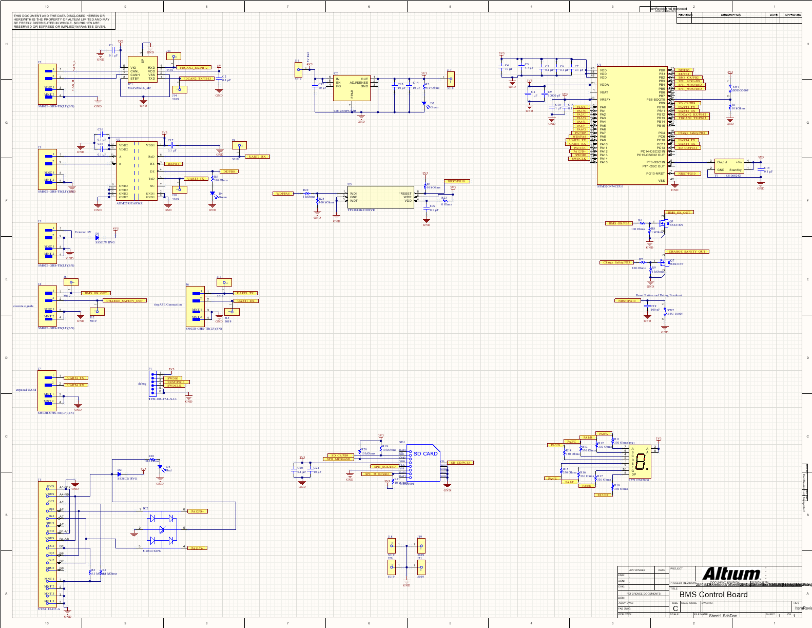
STM32G474 master board that aggregates sensor data, runs the AMS fault state machine, and reports telemetry over vehicle CAN.
RS-485 Thermal Network
Custom master-polled protocol over isolated RS-485, linking 4 distributed thermistor modules for real-time temperature mapping.
Cell-Voltage Chain
8 Enepaq tinyAFEs (2 per segment) daisy-chained over isolated UART, feeding per-cell voltage into the same fault logic.
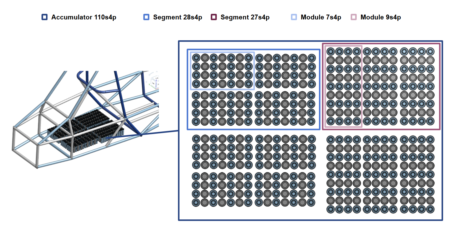
Each segment is removable as a unit, and the harnessing keeps the control board and sensor network accessible without breaking down the whole accumulator.
BMS control board
The control board is built around an STM32G474CEU6, sitting between the sensor network and the rest of
the car. It owns the RS-485 bus to the thermistor modules and the isolated UART link to the cell-voltage
AFE chain, evaluates both against configured thresholds, and drives BMS_OK and
Charge_Safety. Vehicle telemetry goes out over FDCAN2 through an MCP2562-E/MF transceiver.
Both safety outputs are driven through low-side N-channel MOSFETs, so each line is held only while its gate
is actively driven. Gate pulldowns open the safety loop if the board loses power or the MCU resets. I added
a TPS3813K33 window watchdog so a stalled MCU cannot leave the outputs asserted: firmware must service it
inside a valid timing window, and a missed or early kick pulls NRST low. Reset returns the
safety GPIOs to high impedance, releases the MOSFETs, and opens both loops. This makes the safe state an
electrical default instead of a software recovery path. The physical safety loop then latches the trip
while the BMS continues to report its current error state.
Everything crossing into the pack is isolated. The thermistor bus runs through an ADM2795EARWZ, an isolated RS-485 transceiver with fault-protected bus pins, and the cell-voltage data arrives over an isolated UART link, so the low-voltage control side and the 450 V side never share a ground.
For diagnostics, the board has USB-C and SWD for config and flashing, a single-digit display for an at-a-glance fault code without a laptop attached, and a microSD socket for local telemetry logging. Logging is designed to run asynchronously at low priority so a slow card write can never stall the safety loop.
Custom RS-485 thermistor network
Rather than home-running every thermistor back to the control board, four distributed STM32G474 thermistor modules, one per segment, sit on a shared isolated RS-485 bus, a multi-drop daisy chain over a single differential pair. I designed the wire protocol myself: half-duplex and master-polled, so the control board always owns the bus and the remote modules never have to arbitrate. The bus runs at 115200 bps over isolated transceivers, and the wire-time budget for a full four-module poll cycle is about 16 ms. That leaves the bus idle most of the time at the refresh rate the fault logic actually needs. The baud can go up later without touching the protocol.
+------+------+------+------+-----------+--------+--------+
| SOF  | ADDR | CMD  | LEN  |  PAYLOAD  | CRC_HI | CRC_LO |
|  0   |  1   |  2   |  3   |   4..N    |  N+1   |  N+2   |
+------+------+------+------+-----------+--------+--------+
| Field | Size | What it carries |
|---|---|---|
| SOF | 1 byte | Fixed 0xAA sync marker, so a receiver that comes up mid-stream can find a frame boundary. |
| ADDR | 1 byte | 0x00 to 0x03, one per segment module, set in hardware. 0xFF is a broadcast with no reply. |
| CMD | 1 byte | Command identifier. A module's reply is the request with the high bit set, so a response is never mistaken for a poll. |
| LEN | 1 byte | Payload length, zero when there is none. The parser knows how much to read before it reads it. |
| PAYLOAD | LEN bytes | Command-specific. A temperature summary is 8 bytes; a ping response is 1 byte of status flags. |
| CRC | 2 bytes | CRC-16/CCITT-FALSE over bytes 0 through N, high byte first, selected for direct use with the STM32G4's hardware CRC peripheral. |
The command set covers polling for a temperature summary, a ping/health check, pushing threshold
configuration to a module, and a broadcast command to clear latched faults across all four modules at
once. Each module reports back its min, max, and average temperature plus a fault bit field (over-temp,
under-temp, sensor fault, stale data), so the control board's fault logic sees per-segment context
instead of a single aggregate flag. If a module misses three consecutive polls it's marked
COMMS_LOST and treated as a hard fault, but the control board keeps polling the rest of
the chain so one dead node can't stall the bus for everyone else.
The two ends of that bus run different concurrency models, for reasons that come from what each one has to do. The control board runs FreeRTOS because it juggles four interfaces at once, RS-485, CAN, the AFE UART, and USB, with the fault logic sitting on top of all of them. A thermistor module does exactly two things: scan its sensors on a timer, and answer when it is polled. It runs a bare-metal superloop. An RTOS there would buy nothing and add one more thing to audit on a board whose value is being simple enough to trust.
Cell-voltage chain
Cell voltage comes from 8 Enepaq tinyAFEs, two per segment, on their own isolated UART daisy chain, separate from the thermistor bus. Each AFE is referenced to the lowest cell it monitors, and the head AFE in the chain talks to the control board through Enepaq's proprietary-to-UART converter. That voltage data feeds into the same fault logic as the thermal data, so over-temperature and over-voltage conditions are evaluated together rather than as two separate systems bolted side by side.
Cell testing & validation
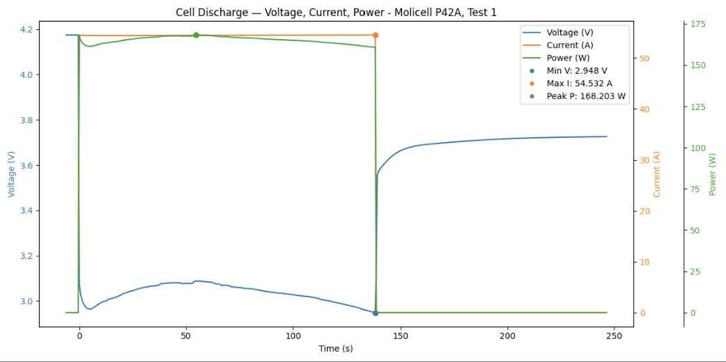
The pack architecture started as arithmetic, and the arithmetic ran off the end of the datasheet. Sizing peak current around the motor we were running at the time put our worst case above the range Molicel characterizes the P42A over, so the published curves could not tell us what a cell would actually do at our peak. That is not something to find out with a finished pack.
So we built a single-cell testbench and measured it. Cells get discharged under profiles shaped like an event rather than a constant-current sweep, at the current the car would really pull, and we watch how far the voltage sags the moment the load lands and how much of it comes back when the load releases.
That measurement is what the pack gets configured against. How far a cell sags decides how much of the pack's nominal voltage is still there at the end of a run, so the series and parallel arrangement has to be chosen from measured behavior rather than a datasheet curve, inside what the Formula-Hybrid Electric rules allow and what the car needs. How hard the same profile heats the cells feeds the cooling design and the temperature thresholds the BMS gets configured with.
Previous accumulator 2024 — 2025
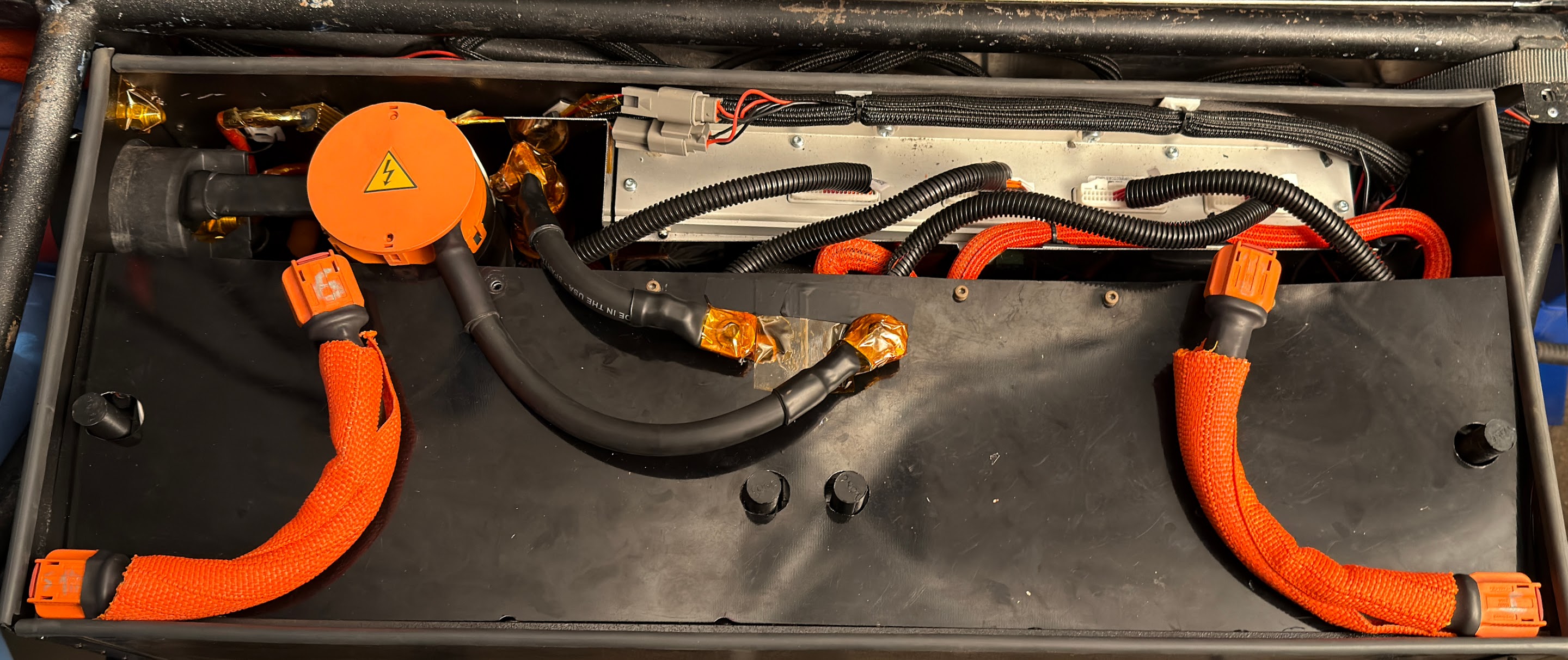
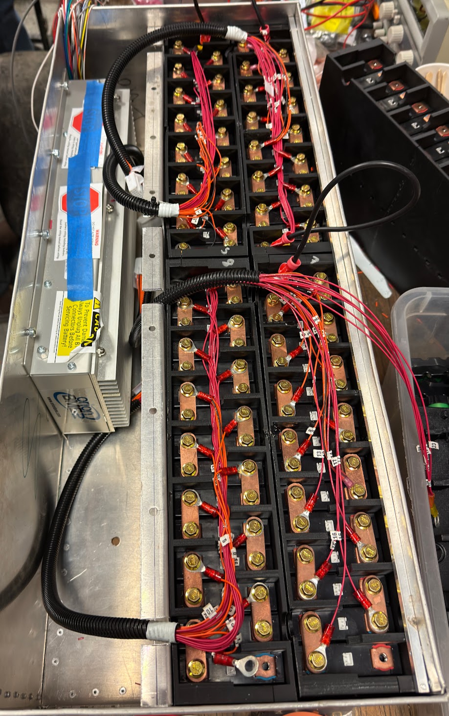
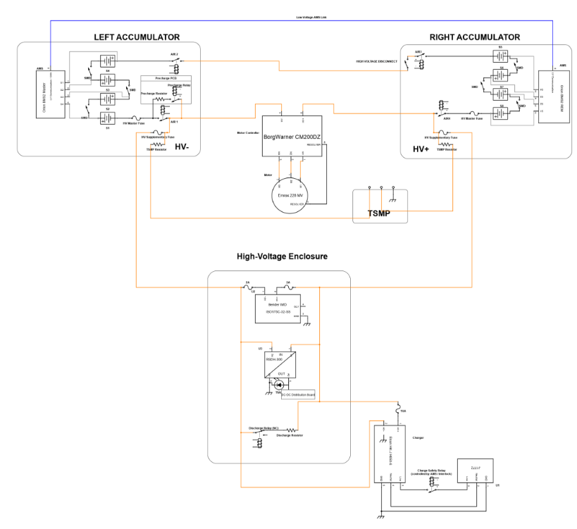
I joined the team as an Electrical Engineer on the previous generation of the pack. My work sat on the high-current side: the path from the cells out to the pack connector, the modules that path runs through, and getting a module built and safely energized for the first time. I also designed the two low-voltage boards the car's safety systems ran through.
First assembly came after months of design and build, and it is the point where the paper pack becomes a real one. Getting a module assembled, checked, and energized for the first time is a deliberate, procedural exercise: it is the first time the safety systems are asked to do their job with live cells behind them rather than a bench supply.
From there the module went into the car's sidepod as a prototype, which tested the mechanical packaging and the high-voltage connections in their real positions and let us run charge and discharge testing under load.
Low-voltage safety boards
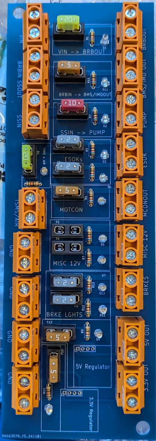
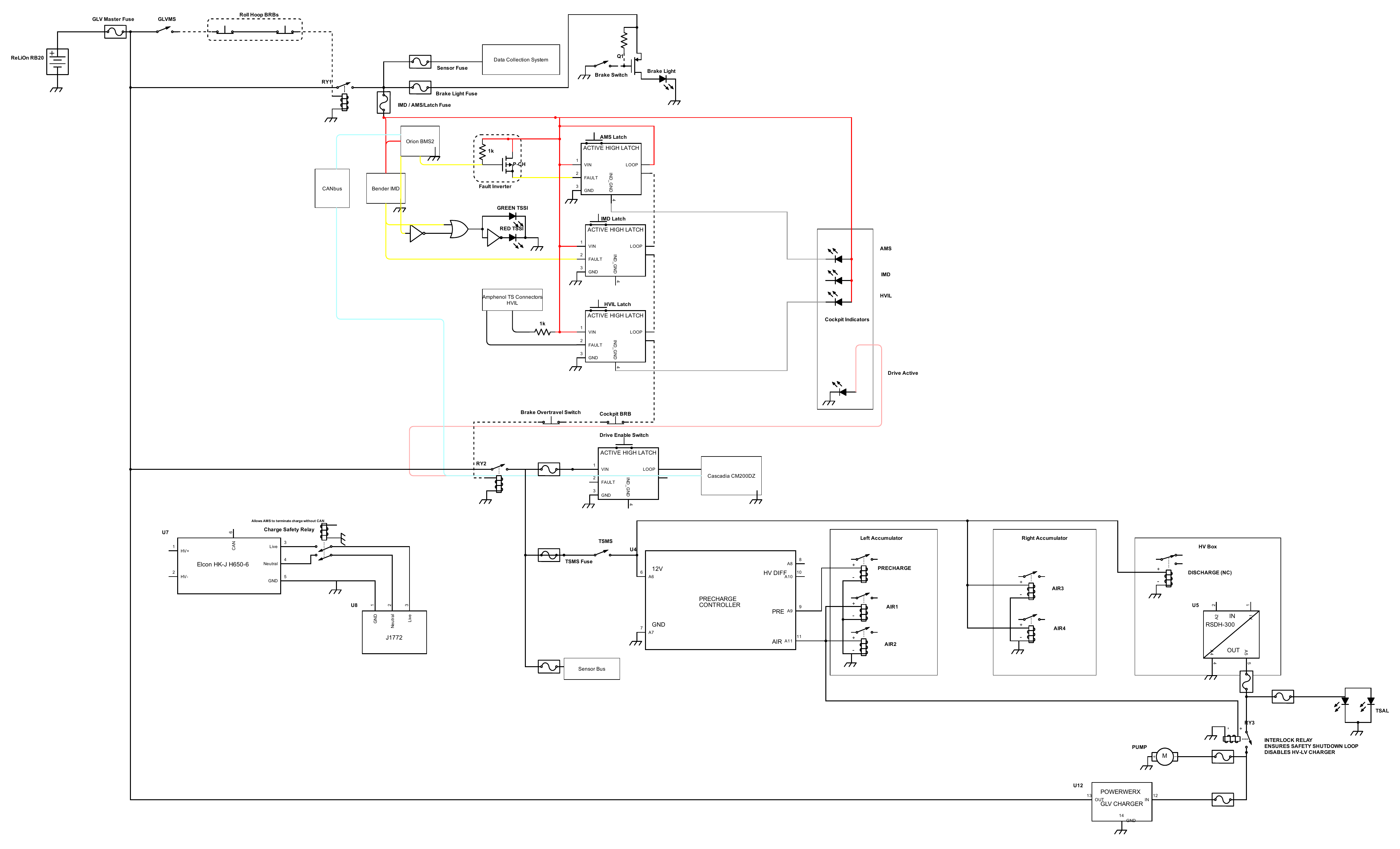
The fusebox splits and protects the car's low-voltage supply. Every circuit gets its own blade fuse with an indicator LED beside it, so a blown fuse is visible at a glance instead of being tracked down with a meter. The same board carries the shutdown-circuit signals alongside the power rails, including the TSMS and AIR lines, the big red button loop, the ESOK line, and the BMS and IMD outputs, plus the 3.3 V and 5 V regulators feeding the boards downstream.
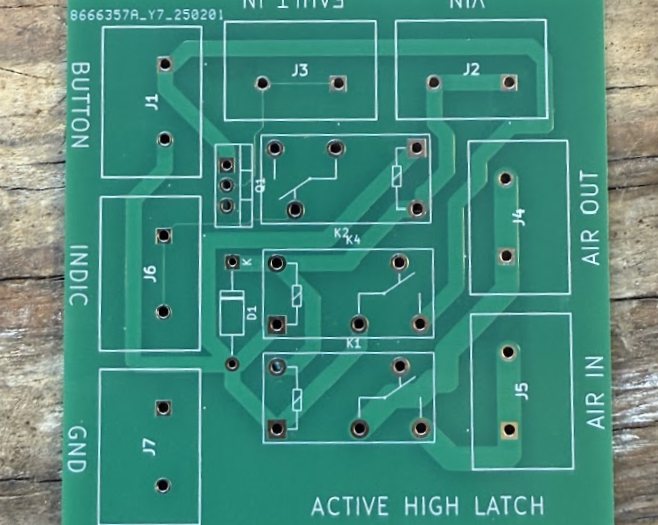
The interlock latches keep the safety loop energized only while no faults are present. I designed active-high and active-low versions so the same latch logic could sit behind sensors of either polarity, covering motor controller, BMS, and high-voltage connection fault signals. Each latch powers up in the disconnected state and only closes once every safety condition is met, and any fault or loss of power drops it immediately. They are fail-safe by construction: the de-energized state is the safe one, so nothing has to run correctly for the car to end up safe.
What I’ve learned
FSAE was the jump from class projects that only have to work once to engineering for a real system. An accumulator has to survive the conditions it was designed for, fit the car, follow the rules, and stay understandable to the people who build, test, and service it. The BMS is not a board in isolation: the control board, the thermistor network, the cell-voltage chain and the safety outputs all have to work together at the moment the car needs them.
The technical work changed the order I think in. The happy path turns out to be the easy part of a protocol. The design decisions live in what happens when a module goes quiet, when a frame arrives corrupted, when a response is late, and none of them would have come out of the feature list.
Leading the program has made the non-schematic parts of engineering just as real. Budget and part availability can change an option, serviceability can rule out an elegant layout, and a competition deadline decides what gets designed now and what is deferred. The team is building a safety-critical system in its spare time while carrying full course loads, so every design has to be something we can finish, validate and support. The lesson is not to remove complexity for its own sake. It is to make the right complexity manageable for the team that has to deliver it.