Overview
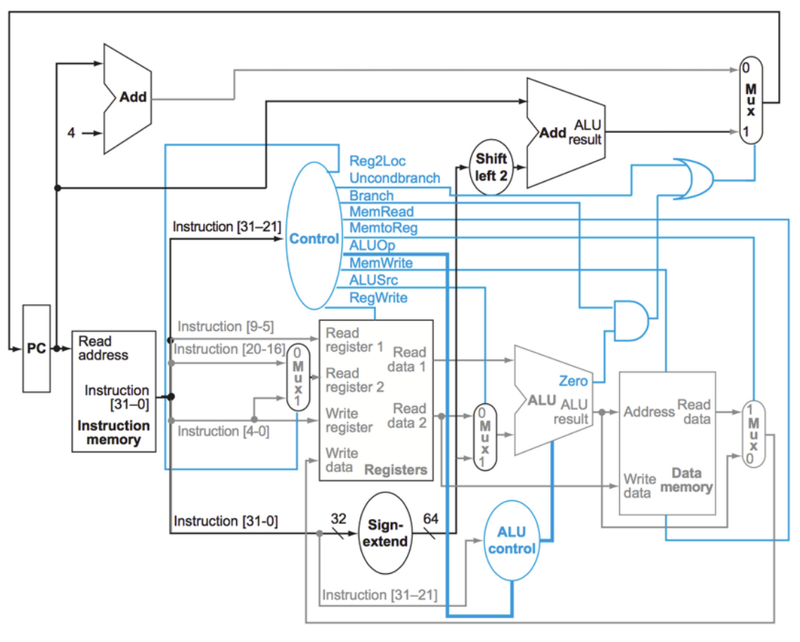
As the term project for my Computer Architecture course, I designed and implemented a simplified ARM-like processor using VHDL. The processor supports a subset of ARM instructions (specifically LEGv8), including arithmetic operations, memory access, and control flow.
The project began with the foundational components: PC, instruction and data memory, register file, and ALU. I first wired these together into a single-cycle architecture to validate basic functionality before transitioning to a pipelined design. That shift introduced challenges around instruction dependencies and timing, which I addressed through hazard detection and data forwarding.
Pipelining the datapath
The pipeline follows the classic five-stage approach: Instruction Fetch, Instruction Decode, Execute, Memory Access, and Write Back. Each stage operates concurrently with the others, creating a processing pipeline that can theoretically complete one instruction per clock cycle. The real complexity comes from data hazards: situations where instructions depend on results from previous instructions still moving through the pipeline.
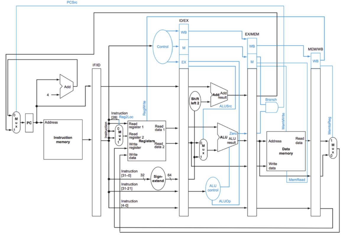
Most of the bugs that actually cost time weren't in the hazard logic itself. Several pipeline registers and internal signals weren't initialized to a known value at reset, so simulations would run clean until a specific reset timing exposed garbage propagating through the datapath. The rest were classic hazard bugs: read-after-write cases where a dependent instruction read a stale register value before forwarding caught up, and write-after-read cases where the register file wrote its new value before an earlier stage had read the old one. Both took cycle-by-cycle waveform tracing to pin down.
library IEEE;
use IEEE.std_logic_1164.all;
use IEEE.numeric_std.all;

entity SingleCycleCPU is
port(clk :in STD_LOGIC;
     rst :in STD_LOGIC;
     --Probe ports used for testing
     --The current address (AddressOut from the PC)
     DEBUG_PC : out STD_LOGIC_VECTOR(63 downto 0);
     --The current instruction (Instruction output of IMEM)
     DEBUG_INSTRUCTION : out STD_LOGIC_VECTOR(31 downto 0);
     --DEBUG ports from other components
     DEBUG_TMP_REGS : out STD_LOGIC_VECTOR(64*4 - 1 downto 0);
     DEBUG_SAVED_REGS : out STD_LOGIC_VECTOR(64*4 - 1 downto 0);
     DEBUG_MEM_CONTENTS : out STD_LOGIC_VECTOR(64*4 - 1 downto 0)
);
end SingleCycleCPU;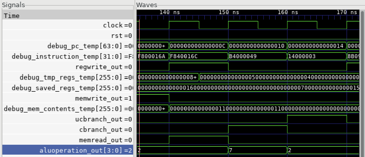
Verification
The debug ports are what let the testbenches check themselves. A testbench loads an instruction sequence, runs it, and compares the register file and memory contents against the end state that sequence should produce, so a failing program reports which value is wrong instead of leaving me to read a waveform and decide. GTKWave came after that, once a check had told me something was broken and I needed to find which stage broke it.
Image credits
- Single-cycle and pipelined datapath diagrams: Patterson, David A., and John L. Hennessy. Computer Organization and Design: The Hardware/Software Interface (Arm® Edition). ISBN 978-0-12-801733-3.
Textbook diagram used for educational purposes under fair use. Code screenshots and simulations are personal development work.