Why build it.
Off-the-shelf keyboards make some decisions for me: the layout, what's on the PCB, the shape of the case. Building one from scratch flips that order. I pick the layout first, decide what goes on the board, and design the case around it instead of the other way around.
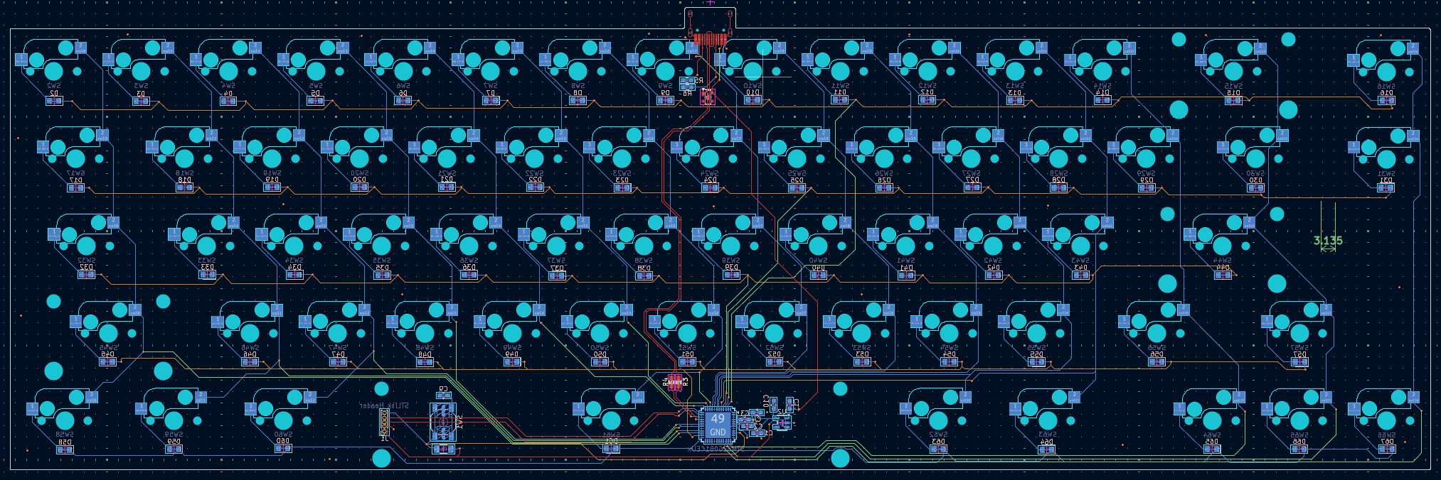
It's also a way to learn the full PCB workflow end to end: laying out the board in KiCad, placing the STM32, routing USB-C with ESD protection, and generating gerbers for fabrication. The appeal is that it's immediately verifiable, either the keyboard works or it doesn't. The 65% layout keeps the build compact, but the arrow cluster stays. That's the one thing I'm not willing to drop.
PCB design.
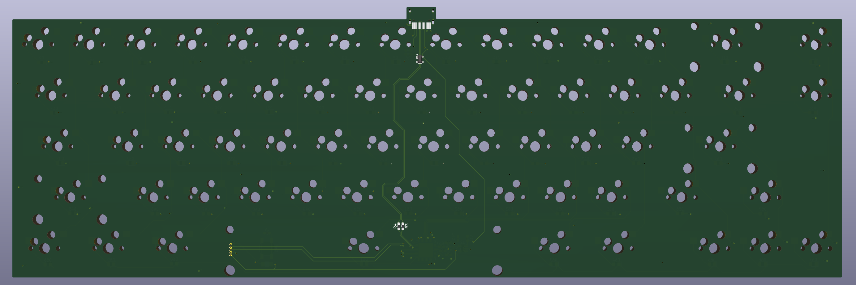
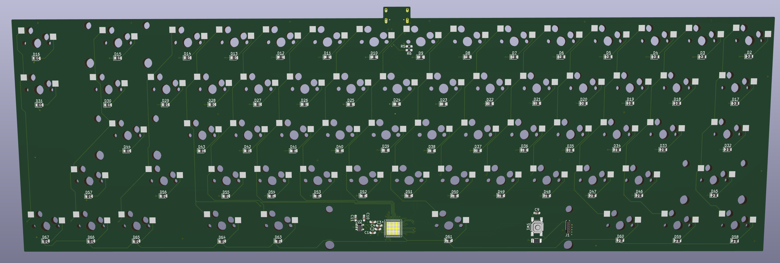
Controller
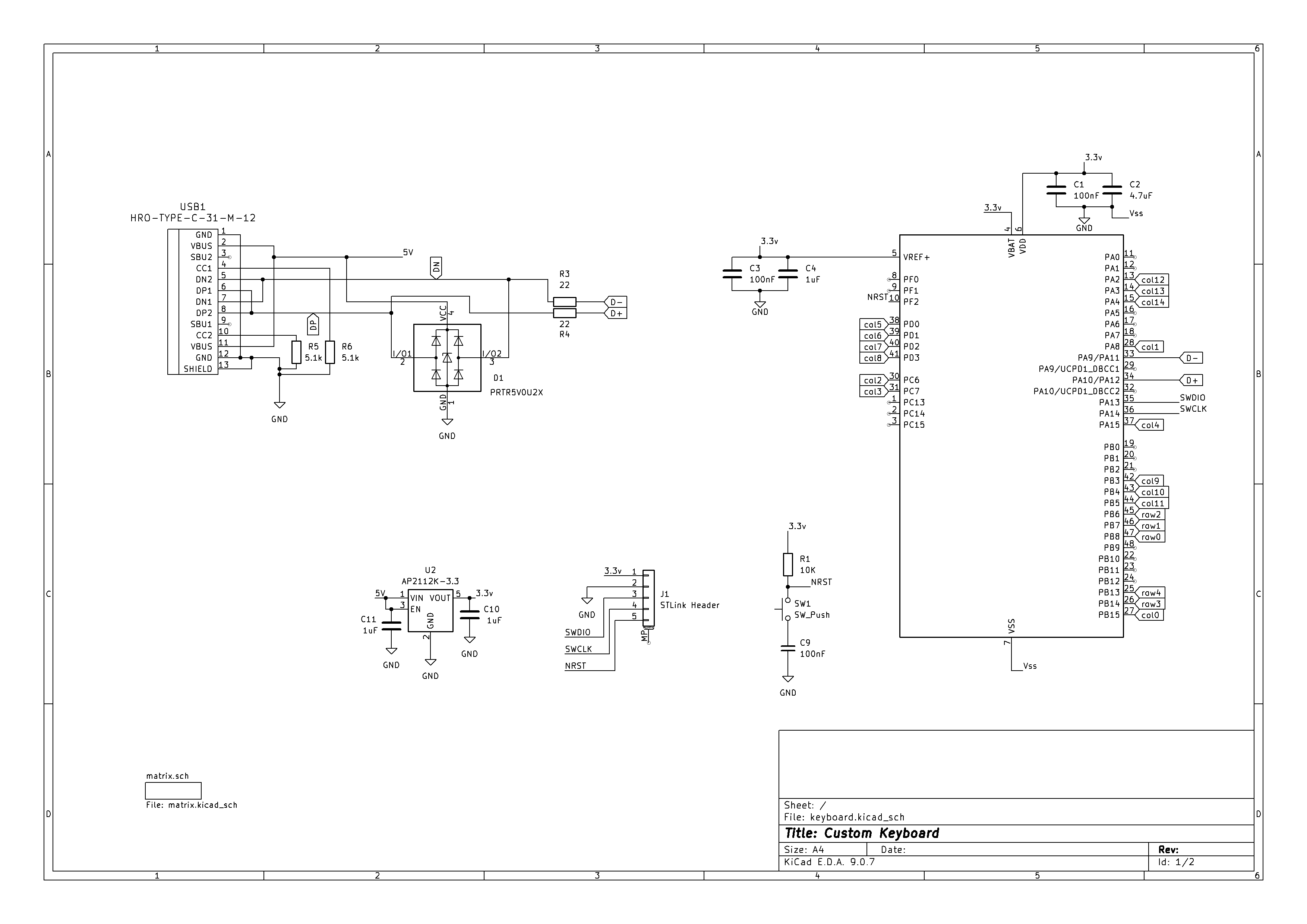
The board is centered on an STM32G0B1CEUx, an ARM Cortex-M0+ with native USB 2.0 full-speed built in. Native USB matters here: the MCU enumerates directly as a USB HID device without a USB-to-serial bridge, keeping the hardware simple and giving QMK full control over the USB descriptor. I'm familiar with the STM32G-family from other projects, so reaching for the G0 here made sense: it has everything a keyboard needs without the cost or complexity of a larger part. QMK supports it via ChibiOS, which handles the low-level RTOS and USB stack.
USB-C and ESD protection
The USB connector is USB-C with ESD protection on the data lines via a PRTR5V0U2X TVS array. Keyboard connectors take a lot of plug cycles and get exposed to whatever static charge walks up to the desk, so protecting the USB differential pair is straightforward insurance.
Hot-swap sockets
The PCB uses hot-swap sockets rather than soldered switches, so I can change switch feel without reflowing the board. From a layout standpoint this means placing socket footprints precisely, keeping the underside of the board clear of traces in the socket area, and orienting each socket consistently so the seating force goes the right direction.
Diode matrix and N-key rollover
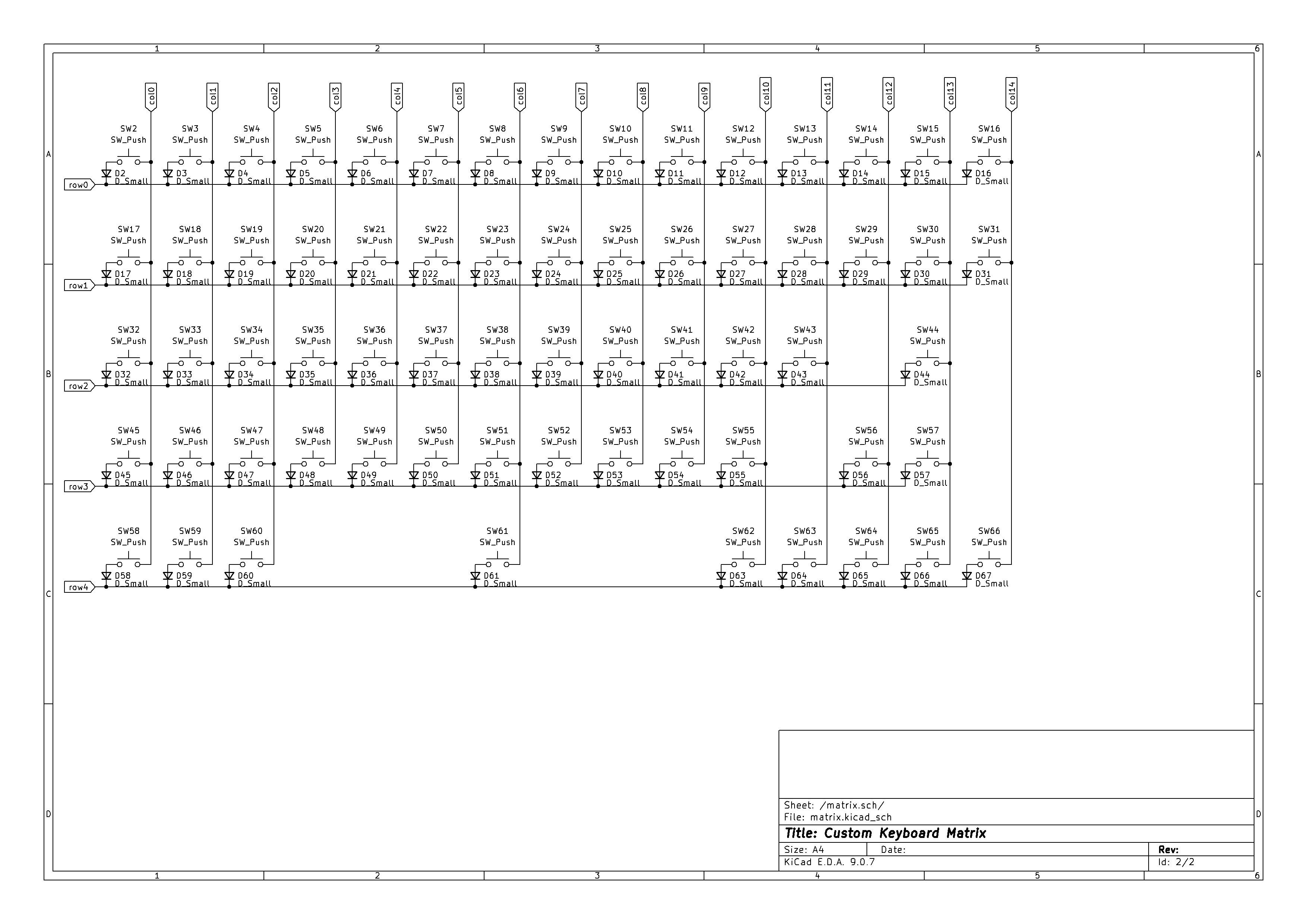
Every switch in the 5×15 grid carries a diode in series, so the scan can't be fooled into a phantom keypress by a reverse path through a fourth key when three corners of a rectangle are held down. Any combination can be held at once, which QMK exposes as N-key rollover over USB HID.
Programming header
The PCB includes an STLink SWD header and a dedicated boot-mode button. During development, that means I can flash firmware and step through code with a debugger attached rather than relying purely on the USB DFU bootloader, a convenience that pays for itself the first time something doesn't behave as expected.
Case and plate.
The case is being designed in Onshape to fit the PCB footprint exactly, targeting CNC-machined aluminum. Aluminum also gives better acoustic control than printed plastic: the weight and rigidity damp the higher-frequency ping that cheaper cases emphasize.
Getting a case machined is a stretch goal after the PCB is verified. For the first functional build I'll use a printed case to confirm fit and feel, then move to aluminum once the layout and PCB are locked in. The Onshape model is parametric, so adjustments from the prototype carry forward without a full redraw.
Where it stands.
The PCB design is complete and ready to send to fabrication. Case design is actively in progress in Onshape. Switch and keycap selection is still open; both will be picked once the board is in hand and the layout is confirmed to feel right.
PCB
Design complete in KiCad. Ready for fabrication.
Case
In progress in Onshape. CNC aluminum is the target; printed prototype first.
Switches & Keycaps
TBD, selecting after the board is in hand and the layout is confirmed.